Basic Usage of 2-Dimensional Physics Simulation Physics2D Library

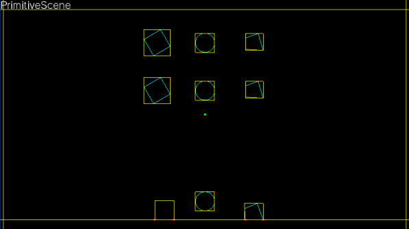
We will check sample scene called "Primitive Scene" to learn how to use 2-dimensional physics simulation Physics2D library.
Please refer "sample/Physics2D/Physics2DSample/BasicScene/PrimitiveScene.cs"

alternate text

Minimal Process of Creating Physics Simulation Scene

The following is minimal process of creating physics simulation scene.

  1. Create the scene class inherit from PhysicsScene
  2. Override InitScene() of the scene class
  3. Call InitScene() inside constructor of the scene class

We will check the code of PrimitiveScene to create the scene class as an example.

  1. Create the scene class inherit from PhysicsScene
using System;
using System.Text;

using Sce.PlayStation.Core;
using Sce.PlayStation.Core.Graphics;
using Sce.PlayStation.Core.Input;
using Sce.PlayStation.Core.Environment;

// Include 2D Physics Framework
using Sce.PlayStation.HighLevel.Physics2D;

public class PrimitiveScene : PhysicsScene
{

}
  1. Override InitScene() of the scene class
using System;
using System.Text;

using Sce.PlayStation.Core;
using Sce.PlayStation.Core.Graphics;
using Sce.PlayStation.Core.Input;
using Sce.PlayStation.Core.Environment;

// Include 2D Physics Framework
using Sce.PlayStation.HighLevel.Physics2D;

public class PrimitiveScene : PhysicsScene
{
        public override void InitScene ()
        {
                // Create an empty simulation scene
                base.InitScene();
        }
}
  1. Call InitScene() inside constructor of the scene class
using System;
using System.Text;

using Sce.PlayStation.Core;
using Sce.PlayStation.Core.Graphics;
using Sce.PlayStation.Core.Input;
using Sce.PlayStation.Core.Environment;

// Include 2D Physics Framework
using Sce.PlayStation.HighLevel.Physics2D;

public class PrimitiveScene : PhysicsScene
{
        public PrimitiveScene()
        {
            InitScene();
        }

        public override void InitScene ()
        {
                // Create an empty simulation scene
                base.InitScene();
        }
}
Minimal setup of physics simulation scene is ready now.

But there are no physics object inside the scene, and simulation will not do anything at all.
Now we should put necessary rigid bodies as the initial state of the scene inside InitScene().

Then we will check the InitScene() and see how to put rigid bodies as the initial state of the scene.

Initial Setup of Rigid Bodies

The following is basic process of initial setup of rigid bodies.
  1. Create the collision shape
  2. Create the rigid body linked with the collision shape

Create the Collision Shape

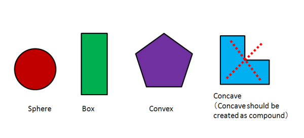
Basically collision shape should be convex shape including sphere, box and usual convex.
Maximum number of vertices of convex shape is 30. But when you modify source codes, you can change this upper limitation.
However, simulation cost will increase in the case that convex contains a lot of vertices.

alternate text
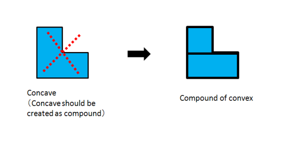
Concave shape cannot be set to the collision shape directly.
Concave shape should be treated as compound of multiple rigid bodies.
alternate text
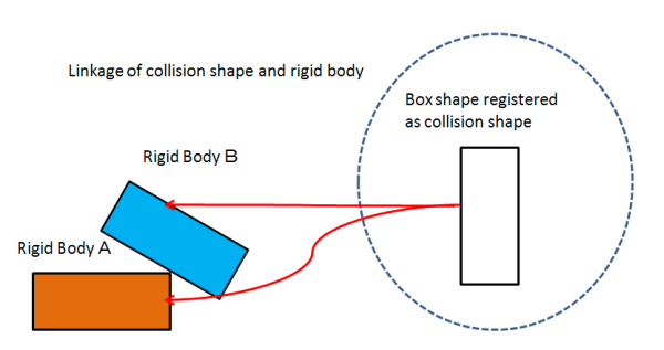
Collision shapes of the scene are registered to sceneShapes.
At the same time, please do not forget set numShape and make sure that numShape is equals to number of collision shapes.

Now we will check the way to set collision shapes inside PrimitiveScene.
public override void InitScene ()
{
        // Create an empty simulation scene
        base.InitScene();

        ...
        ...
        ...

        // Box Shape Setting PhysicsShape( "width", "height" )
        Vector2 wall_width = new Vector2(50, 8);
        sceneShapes[0] = new PhysicsShape(wall_width);

        Vector2 wall_height = new Vector2(8, 30);
        sceneShapes[1] = new PhysicsShape(wall_height);

        Vector2 box_width = new Vector2(2.0f, 2.0f);
        sceneShapes[2] = new PhysicsShape(box_width);

        // Sphere Shape Setting PhysicsShape( "radius" )
        float sphere_width = 2.0f;
        sceneShapes[3] = new PhysicsShape(sphere_width);


        Vector2[] test_point = new Vector2[10];

        for (int i = 0; i < 10; i++)
        {
            test_point[i] = new Vector2(rand_gen.Next(-1000, 1000), rand_gen.Next(-1000, 1000)) * 2.0f / 1000.0f;
        }

        // Convex Shape Setting (by using random points)
        sceneShapes[4] = PhysicsShape.CreateConvexHull(test_point, 10);

        numShape = 5;

        ...
        ...
        ...
}

Example of Box Shape

Half of width and height is given to the constructor of PhysicsShape.

Vector2 wall_width = new Vector2(50, 8);
sceneShapes[0] = new PhysicsShape(wall_width);

Example of Sphere Shape

Radius is given to the constructor of PhysicsShape.

float sphere_width = 2.0f;
sceneShapes[3] = new PhysicsShape(sphere_width);

Example of Convex Shape

We create 10 vertices as random points at first, and convex hull is created based on these random points.

Vector2[] test_point = new Vector2[10];

for (int i = 0; i < 10; i++)
{
        test_point[i] = new Vector2(rand_gen.Next(-1000, 1000), rand_gen.Next(-1000, 1000)) * 2.0f / 1000.0f;
}

sceneShapes[4] = PhysicsShape.CreateConvexHull(test_point, 10);

CreateConvexHull creates convex hull from several random points here.

Number of Collision Shapes

We can increment one by one for each collision shapes, but we set numShape after all collision shapes are registered here.

numShape = 5;
All things of registration of collision shapes for PrimitiveScene are done here.

But these are only for registration of collision shapes and it does not say that there are rigid bodies.
Next we will create rigid bodies based on registered collision shapes.

Create the rigid body linked with the collision shape

There are several types for rigid bodies.
Dynamic Rigid Body

  • Usual rigid body used well
  • Has velocity and acceleration and move in a scene

Static Rigid Body

  • Does not move at all from the start of the scene to the end
  • Calculated assuming that it has infinite mass

Kinematic Rigid Body

  • Be set to the state of rest or moved compulsorily temporarily
  • Calculated assuming that it has infinite mass temporarily

Trigger Rigid Body

  • Used for the purpose of detecting whether any rigid bodies having gone into a certain domain in a scene
  • Although there is collision detection, but there is not collision response
First of all, it is necessary to clarify which type of rigid body we would like to create.
Static rigid body is used when creating the wall or floor which do not move at all. On the other hand, dynamic rigid body is used when creating a ball which rolls on the floor.

When creating a rigid body, it is common to set the type of the above-mentioned rigid body, and to arrange initial state of it.

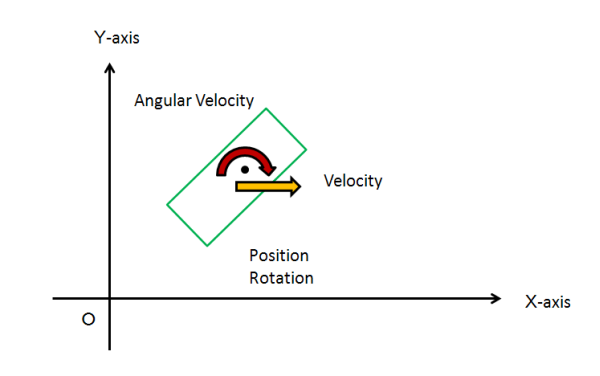
Attribute Used to Initial Setting of a Rigid Body

  • Mass
  • Position
  • Rotation
  • Velocity
  • Angular Velocity
alternate text
Now we will check how rigid bodies are arranged for the initial state of PrimitiveScene.
First of all, the rigid body used as a wall, a floor, and ceiling is created as a static rigid body in the scene.
These rigid bodies do not move at all from the start to the end.

Example of Setup of Static Rigid Body

public override void InitScene()
{
        ...
        ...
        ...

    // Create static walls to limit the range of action of active rigid sceneBodies
    {
        // new PhysicsBody( "shape of the body",  "mass of the body(kg)" )
        sceneBodies[numBody] = new PhysicsBody(sceneShapes[0], PhysicsUtility.FltMax);

        // Set the position & the rotation
        sceneBodies[numBody].position = new Vector2(0, -wall_height.Y);
        sceneBodies[numBody].rotation = 0;

        // Make shapeIndex consistent with what we set as convex shape
        sceneBodies[numBody].shapeIndex = 0;
        numBody++;

        sceneBodies[numBody] = new PhysicsBody(sceneShapes[1], PhysicsUtility.FltMax);
        sceneBodies[numBody].position = new Vector2(wall_width.X, 0);
        sceneBodies[numBody].rotation = 0;
        sceneBodies[numBody].shapeIndex = 1;
        numBody++;

        sceneBodies[numBody] = new PhysicsBody(sceneShapes[1], PhysicsUtility.FltMax);
        sceneBodies[numBody].position = new Vector2(-wall_width.X, 0);
        sceneBodies[numBody].rotation = 0;
        sceneBodies[numBody].shapeIndex = 1;
        numBody++;

        sceneBodies[numBody] = new PhysicsBody(sceneShapes[0], PhysicsUtility.FltMax);
        sceneBodies[numBody].position = new Vector2(0, wall_height.Y);
        sceneBodies[numBody].rotation = 0;
        sceneBodies[numBody].shapeIndex = 0;
        numBody++;
    }

        ...
        ...
        ...
}

Here, the static rigid body used as a floor is set up.
sceneBodies[numBody] = new PhysicsBody(sceneShapes[0], PhysicsUtility.FltMax);
sceneBodies[numBody].position = new Vector2(0, -wall_height.Y);
sceneBodies[numBody].rotation = 0;
sceneBodies[numBody].shapeIndex = 0;
numBody++;
  1. Box shape as collision shape sceneShape[0] and infinite mass PhysicsUtility.FltMax are given to the constructor of PhysicsBody
  2. Vector2(0, -wall_height.Y) is set to position
  3. 0 is set to rotation
  4. Index is set to shapeIndex as well as the constructor of PhysicsBody
  5. Increment numBody which represents number of rigid bodies inside the scene
A setup of a wall and a ceiling as the static rigid body is also the same.

Since the collision shape of the rigid body of a floor and a ceiling is the same here, the collision shape associated becomes the same.
Because collision shape can be related with two or more rigid bodies, please take care not to create two or more same collision shape.

alternate text

Next we will create a sphere, box and convex as a dynamic rigid body which can move freely in a scene.

Example of Setup of Dynamic Rigid Body

// Create dynamic rigid sceneBodies
{
    // Create a box-shaped dynamic rigid body
    {
        sceneBodies[numBody] = new PhysicsBody(sceneShapes[2], 1.0f);
        sceneBodies[numBody].position = new Vector2(-10.0f, -5.0f);
        sceneBodies[numBody].rotation = PhysicsUtility.GetRadian(30.0f);
        sceneBodies[numBody].shapeIndex = 2;
        numBody++;
    }

    // Create a sphere-shaped dynamic rigid body
    {
        sceneBodies[numBody] = new PhysicsBody(sceneShapes[3], 1.0f);
        sceneBodies[numBody].position = new Vector2(0.0f, -5.0f);
        sceneBodies[numBody].rotation = 0;
        sceneBodies[numBody].shapeIndex = 3;
        sceneBodies[numBody].colFriction = 0.01f;
        numBody++;
    }

    // Create a convex-shaped dynamic rigid body
    {
        sceneBodies[numBody] = new PhysicsBody(sceneShapes[4], 1.0f);
        sceneBodies[numBody].position = new Vector2(10.0f, -5.0f);
        sceneBodies[numBody].rotation = 0;
        sceneBodies[numBody].shapeIndex = 4;
        numBody++;
    }
}

Here the box as dynamic rigid body is set up.

sceneBodies[numBody] = new PhysicsBody(sceneShapes[2], 1.0f);
sceneBodies[numBody].position = new Vector2(-10.0f, -5.0f);
sceneBodies[numBody].rotation = PhysicsUtility.GetRadian(30.0f);
sceneBodies[numBody].shapeIndex = 2;
numBody++;
  1. Box shape as collision shape sceneShape[2] and mass 1.0f are given to the constructor of PhysicsBody
  2. Vector2(-10.0f, -5.0f) is set to position
  3. PhysicsUtility.GetRadian(30.0f) is set to rotation ( in radian )
  4. Index is set to shapeIndex as well as the constructor of PhysicsBody
  5. Increment numBody which represents number of rigid bodies inside the scene
A setup of a sphere and convex as the dynamic rigid body is also the same.

Here the sphere as dynamic rigid body is set up.
sceneBodies[numBody] = new PhysicsBody(sceneShapes[3], 1.0f);
sceneBodies[numBody].position = new Vector2(0.0f, -5.0f);
sceneBodies[numBody].rotation = 0;
sceneBodies[numBody].shapeIndex = 3;
sceneBodies[numBody].colFriction = 0.01f;
numBody++;
  1. Box shape as collision shape sceneShape[3] and mass 1.0f are given to the constructor of PhysicsBody
  2. Vector2(0.0f, -5.0f) is set to position
  3. 0 is set to rotation
  4. Index is set to shapeIndex as well as the constructor of PhysicsBody
  5. Collision Friction 0.01 is set
  6. Increment numBody which represents number of rigid bodies inside the scene

Here the convex as dynamic rigid body is set up.
sceneBodies[numBody] = new PhysicsBody(sceneShapes[4], 1.0f);
sceneBodies[numBody].position = new Vector2(10.0f, -5.0f);
sceneBodies[numBody].rotation = 0;
sceneBodies[numBody].shapeIndex = 4;
numBody++;
  1. Box shape as collision shape sceneShape[4] and mass 1.0f are given to the constructor of PhysicsBody
  2. Vector2(10.0f, -5.0f) is set to position
  3. 0 is set to rotation
  4. Index is set to shapeIndex as well as the constructor of PhysicsBody
  5. Increment numBody which represents number of rigid bodies inside the scene
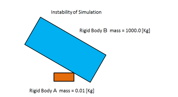
In addition, in the case of a dynamic rigid body, cautions are required for the scale of the rigid body containing mass.

alternate text
When the rigid bodies of different mass scales collide, the instability of simulation may arise.
About the case of dynamic rigid body, it is desirable to create a rigid body in the following ranges as a rough standard.
  • mass scale : 0.2[Kg] - 20.0[Kg]
  • length scale: 0.2[m] - 20.0[m]
Next we will create the kinematic rigid body which is stopped compulsorily temporarily.

Example of Setup of Kinematic Rigid Body

 // Create a kinematic rigid body whose shape is box
{
    sceneBodies[numBody] = new PhysicsBody(sceneShapes[2], 1.0f);
    sceneBodies[numBody].position = new Vector2(-10.0f, 15.0f);
    sceneBodies[numBody].rotation = PhysicsUtility.GetRadian(30.0f);
    sceneBodies[numBody].shapeIndex = 2;
    sceneBodies[numBody].SetBodyKinematic();
    index0 = numBody++;
}

// Create a sphere-shaped kinematic rigid body
{
    sceneBodies[numBody] = new PhysicsBody(sceneShapes[3], 1.0f);
    sceneBodies[numBody].position = new Vector2(0.0f, 15.0f);
    sceneBodies[numBody].rotation = 0;
    sceneBodies[numBody].shapeIndex = 3;
    sceneBodies[numBody].colFriction = 0.01f;
    sceneBodies[numBody].SetBodyKinematic();
    index1 = numBody++;
}

// Create a convex-shaped kinematic rigid body
{
    sceneBodies[numBody] = new PhysicsBody(sceneShapes[4], 1.0f);
    sceneBodies[numBody].position = new Vector2(10.0f, 15.0f);
    sceneBodies[numBody].rotation = 0;
    sceneBodies[numBody].shapeIndex = 4;
    sceneBodies[numBody].SetBodyKinematic();
    index2 = numBody++;
}
Although the kinematic rigid body used as a box is set up here, it is the procedure almost same as a setup of a dynamic rigid body.
A difference is a portion which calls SetBodyKinematic().
sceneBodies[numBody] = new PhysicsBody(sceneShapes[2], 1.0f);
sceneBodies[numBody].position = new Vector2(-10.0f, 15.0f);
sceneBodies[numBody].rotation = PhysicsUtility.GetRadian(30.0f);
sceneBodies[numBody].shapeIndex = 2;
sceneBodies[numBody].SetBodyKinematic();
index0 = numBody++;
  1. Box shape as collision shape sceneShape[2] and mass 1.0f are given to the constructor of PhysicsBody
  2. Vector2(-10.0f, 15.0f) is set to position
  3. PhysicsUtility.GetRadian(30.0f) is set to rotation (in radian)
  4. Index is set to shapeIndex as well as the constructor of PhysicsBody
  5. Call SetBodyKinematic() to change for the kinematic rigid body and necessary information set as the dynamic rigid body are stored
  6. Increment numBody which represents number of rigid bodies inside the scene
A setup of a sphere and a convex as the kinematic rigid body is also the same.

In addition, it can be returned to original dynamic rigid body (stored necessary information) is possible for kinematic rigid body.

In PrimitiveScene, the rigid body once set as the kinematic rigid body by a button input is returned to a dynamic rigid body, or it is again changed to the kinematic rigid body.
This is why index0 is saved for the kinematic rigid body setting.

// Game controller handling
public override void KeyboradFunc(GamePadButtons button)
{
    switch (button)
    {
        case GamePadButtons.Square:

                //
            // isKinematicOrStatic() checks the mass of the rigid body and determines whether a body is kinematic or static
            // backToDynamic() cannot be called for rigid sceneBodies not set up with setKinematic()
            //

            if (sceneBodies[index0].IsKinematic())
                sceneBodies[index0].BackToDynamic();
            else
                sceneBodies[index0].SetBodyKinematic();

            if (sceneBodies[index1].IsKinematic())
                sceneBodies[index1].BackToDynamic();
            else
                sceneBodies[index1].SetBodyKinematic();

            if (sceneBodies[index2].IsKinematic())
                sceneBodies[index2].BackToDynamic();
            else
                sceneBodies[index2].SetBodyKinematic();

            break;
        default:
            break;
    }
}
It checks whether a rigid body is a kinematic rigid body by IsKinematic API, and if it is a kinematic rigid body, the stored information is returned and it is made to change to a dynamic rigid body.
Also in order to return the stored information, it is necessary to set a kinematic rigid body as a dynamic rigid body at first.
Please set up the rigid body as a static rigid body from the beginning if it will not be changed to a dynamic rigid body.

Characteristic of the Scene Setup

We checked the initial arrangement of a rigid body in InitScene(). Next we will see setup of the characteristic of the scene used by InitScene().

public override void InitScene ()
{
        // Create an empty simulation scene
        base.InitScene();
        sceneName = "PrimitiveScene";

        // Set the restitution coefficient a bit stronger
        this.restitutionCoeff = 0.8f;

sceneName contains the string which represents the name of scene, and it is set as "PrimitiveScene".

this.restitutionCoeff = 0.8f;

The coefficient of rebound to rebounding which is the characteristic of a scene is set up, and rebounding is set as the scene which arises exactly.

The following values can be set up as a parameter which determines the characteristic of a collision within a scene.
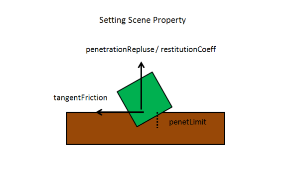
  • float penetrationRepulse (default 0.2f) ... Acceleration factor of the restitution to the penetration of collision
  • float penetLimit (default 0.03f) ... Tolerance to the penetration of collision
  • float tangentFriction (default 0.3f) ... Coefficient of friction of the tangential adjusting to rebounding
  • float restitutionCoeff (default 0.0f) ... Coefficient of rebound to rebounding
alternate text
By changing these values, it is possible to become a scene which rebounding tends to carry out, to become a scene which rebounding cannot carry out easily, or to make it a scene without friction.
There is a sample "sample/Physics2D/Physics2DSample/TutorialScene/ScenePropertyScene.cs", please refer it.

Sleep of Rigid Body


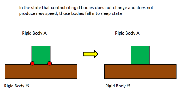
In order to reduce simulation cost, when the rigid body is in the state where it can be considered that it is not moving mostly but is still standing, a rigid body goes into a sleep state.
When a rigid body is in sleep status, collision detection and collision response for it will be ignored and not treated.

In PrimitiveScene, collision between the floor and the rigid body in contact with its floor will not be treated for sleep status.
However, when a new collision occurs and velocity is produced, it makes a rigid body wake up from sleep state.

alternate text
In addition, when it is a state of rest compulsorily because of the static rigid body or the kinematic rigid body, it is always considered as a sleep state.

Rendering of Rigid Body

Rendering of rigid body is explained shortly. About rendering itself, please refer the documentation of Graphics samples.
Here we will just check parts which are related to Physics2D.

Generally, rendering of a rigid body is done based on the collision shape set to the rigid body.
As mentioned already, collision shape is registered to sceneShapes. And sceneShapes is array of PhsyicsShape.

Preparation of Vertex Buffer

First of all, vertex buffer given to shader program is required.

public class PrimitiveScene : PhysicsScene
{
    // Vertex Buffer for Body Rendering
    private VertexBuffer[] vertices = new VertexBuffer[100];
Though the number of collision shapes does not exceed one hundred for PrimitiveScene、we will define vertex buffer for one hundred collision shapes as a temporal here.
Vertex buffer can be shared rigid bodies which have the same collision shape and it is not necessary to prepare for each rigid bodies.
This is just for PrimitiveScene, and it may be necessary to prepare vertex buffer for each rigid bodies in the case that texture mapping is used for rendering rigid bodies.

In the next, we will create vertex buffer by giving number and format of vertices.
public PrimitiveScene()
{
    // Simulation Scene Set Up
    InitScene();

    // Setup for Rendering Object
    for (int i = 0; i < numShape; i++)
    {
        if (sceneShapes[i].numVert == 0)
        {
            vertices[i] = new VertexBuffer(37, VertexFormat.Float3);
        }
        else
        {
            vertices[i] = new VertexBuffer(sceneShapes[i].numVert + 1, VertexFormat.Float3);
        }

Structure of Collision Shape PhysicsShape

Here we will check the structure of PhysicsShape.

public partial class PhysicsShape
{
    public int numVert;

    public Vector2[] vertList = new Vector2[30];
        ...
        ...
        ...
}
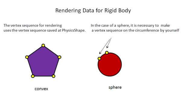
Although this is a part of definition, PhysicsShape holds numVert which represents the number of vertices, and vertList which actually saves a vertex sequence.
Although rendering should be done based on this definition, in the case of numVert==0, it is setting of the sphere, and cautions are required for the point that the radius is set as vertList[0].X.
alternate text

This is the setting of vertices for vertex buffer based on the definition of PhysicsShape.

// Line Rendering for Object
private void MakeLineListConvex(PhysicsShape con, VertexBuffer vertices)
{

    if (con.numVert == 0)
    {
        float[] vertex = new float[3 * 37];

        int i = 0;
        float rad = con.vertList[0].X;

        for (float th1 = 0.0f; th1 < 360.0f; th1 = th1 + 10.0f)
        {
            float th1_rad = th1 / 180.0f * PhysicsUtility.Pi;

            float x1 = rad * (float)Math.Cos(th1_rad);
            float y1 = rad * (float)Math.Sin(th1_rad);

            vertex[3 * i + 0] = x1;
            vertex[3 * i + 1] = y1;
            vertex[3 *  i + 2] = 0.0f;
            i++;
        }

        vertex[3 * i + 0] = vertex[3 * 0 + 0];
        vertex[3 * i + 1] = vertex[3 * 0 + 1];
        vertex[3 * i + 2] = vertex[3 * 0 + 2];

        vertices.SetVertices(0, vertex);

    }
    else
    {
        float[] vertex = new float[3 * (con.numVert + 1)];

        int i;

        for (i = 0; i < con.numVert; i++)
        {
            Vector2 v1;
            v1 = con.vertList[i];

            vertex[3 * i + 0] = v1.X;
            vertex[3 * i + 1] = v1.Y;
            vertex[3 * i + 2] = 0.0f;
        }

        vertex[3 * i + 0] = vertex[3 * 0 + 0];
        vertex[3 * i + 1] = vertex[3 * 0 + 1];
        vertex[3 * i + 2] = vertex[3 * 0 + 2];

        vertices.SetVertices(0, vertex);
    }
}
We divide cases into the case of con.numVert == 0 and others.
This is because information is held in the special format in the case of the sphere as stated.
In the case of a sphere, since only the information on a radius is saved inside the PhysicsShape instance, we have to generate the vertex sequence for rendering by ourself.
Then, a vertex sequence is made from taking up a number of points on the circumference based on this radius.
Here vertices are generated on 36 vertices of the 10-degree unit from 0 degree to 350 degrees, and the coordinates same at the last as the first vertex, it becomes a total of 37 vertices.

On the other hand, for box or general convex, the vertex sequence currently held at the PhysicsShape instance is set to a vertex buffer.

Acquisition of Vertex Data in The Case of Sphere

if (con.numVert == 0)
{
    float[] vertex = new float[3 * 37];

    int i = 0;
    float rad = con.vertList[0].X;

    for (float th1 = 0.0f; th1 < 360.0f; th1 = th1 + 10.0f)
    {
        float th1_rad = th1 / 180.0f * PhysicsUtility.Pi;

        float x1 = rad * (float)Math.Cos(th1_rad);
        float y1 = rad * (float)Math.Sin(th1_rad);

        vertex[3 * i + 0] = x1;
        vertex[3 * i + 1] = y1;
        vertex[3 * i + 2] = 0.0f;
        i++;
    }

    vertex[3 * i + 0] = vertex[3 * 0 + 0];
    vertex[3 * i + 1] = vertex[3 * 0 + 1];
    vertex[3 * i + 2] = vertex[3 * 0 + 2];

    vertices.SetVertices(0, vertex);

}
Although the buffer of vertices used for drawing has three-dimensional coordinates, since the direction of Z-axis is disregarded, 0.0 f is always specified as the Z coordinate.
In order to render lines, the coordinates same as the last vertex as the first vertex are given.

Acquisition of Vertex Data in The Case of Box or General Convex

else
{
    float[] vertex = new float[3 * (con.numVert + 1)];

    int i;

    for (i = 0; i < con.numVert; i++)
    {
        Vector2 v1;
        v1 = con.vertList[i];

        vertex[3 * i + 0] = v1.X;
        vertex[3 * i + 1] = v1.Y;
        vertex[3 * i + 2] = 0.0f;
    }

    vertex[3 * i + 0] = vertex[3 * 0 + 0];
    vertex[3 * i + 1] = vertex[3 * 0 + 1];
    vertex[3 * i + 2] = vertex[3 * 0 + 2];

    vertices.SetVertices(0, vertex);
}

In order to render lines, the coordinates same as the last vertex as the first vertex are given.

Rendering of shape of rigid bodies


It is necessary for rendering of an actual scene not only to to render shape, but to render it according to change of the position in each frame of a rigid body's position or rotation.
Therefore, it is necessary using the value of position, rotation, localPosition, and localRotation of a rigid body to set up the conversion matrix used for rendering.
This matrix is a matrix for changing into the vertex sequence which actually reflected the position of a rigid body, the angle, etc. from the vertex sequence which shows the shape of a basis.
If it is not the case of compound, localPosition and localRotation can be ignored by considering only position and rotation.

alternate text
// Draw objects
public override void DrawAllBody(ref GraphicsContext graphics, ref ShaderProgram program, Matrix4 renderMatrix, int click_index)
{
    for (int j = 0; j < numShape; j++)
    {
        graphics.SetVertexBuffer(0, vertices[j]);

        for (int i = 0; i < numBody; i++)
        {
            uint index = sceneBodies[i].shapeIndex;

            if (j != index) continue;

            Matrix4 rotationMatrix = Matrix4.RotationZ(sceneBodies[i].rotation);

            Matrix4 transMatrix = Matrix4.Translation(
                new Vector3(sceneBodies[i].position.X, sceneBodies[i].position.Y, 0.0f));

            Matrix4 local_rotationMatrix = Matrix4.RotationZ(sceneBodies[i].localRotation);

            Matrix4 local_transMatrix = Matrix4.Translation(
                new Vector3(sceneBodies[i].localPosition.X, sceneBodies[i].localPosition.Y, 0.0f));

            Matrix4 WorldMatrix = renderMatrix * transMatrix * rotationMatrix * local_transMatrix * local_rotationMatrix;

            program.SetUniformValue(0, ref WorldMatrix);

            if (i == click_index)
            {
                Vector3 color = new Vector3(1.0f, 0.0f, 0.0f);
                program.SetUniformValue(1, ref color);
            }
            else
            {
                Vector3 color = new Vector3(0.0f, 1.0f, 1.0f);
                program.SetUniformValue(1, ref color);
            }

            if (sceneShapes[index].numVert == 0)
                graphics.DrawArrays(DrawMode.LineStrip, 0, 37);
            else
                graphics.DrawArrays(DrawMode.LineStrip, 0, sceneShapes[index].numVert + 1);
        }

    }
}
We will check the code in order.
First half contains a setup of the world matrix for a setup of a shader program, or a view matrix.
Please refer Graphics sample for setting of a shader program.

Matrix4 rotationMatrix = Matrix4.RotationZ(sceneBodies[i].rotation);

Matrix4 transMatrix = Matrix4.Translation(
    new Vector3(sceneBodies[i].position.X, sceneBodies[i].position.Y, 0.0f));

Matrix4 local_rotationMatrix = Matrix4.RotationZ(sceneBodies[i].localRotation);

Matrix4 local_transMatrix = Matrix4.Translation(
    new Vector3(sceneBodies[i].localPosition.X, sceneBodies[i].localPosition.Y, 0.0f));

Matrix4 WorldMatrix = renderMatrix * transMatrix * rotationMatrix * local_transMatrix * local_rotationMatrix;

program.SetUniformValue(0, ref WorldMatrix);
Above matrix calculation uses (transMatrix * rotationMatrix * local_transMatrix * local_rotationMatrix).
If it is not the case of compound, it is enough to consider only (transMatrix * rotationMatrix).

Multiplication will be performed in order of the following and each original vertex of the collision shape set as the rigid body in drawing will be changed into the vertex reflecting a current position, an rotation, etc. of the rigid body.
  1. local_rotationMatrix
  2. local_transMatrix
  3. rotationMatrix
  4. transMatrix

When setting up the matrix of conversion, the rest should just render by giving the vertex of the original collision shape to shader.

if (sceneShapes[index].numVert == 0)
    graphics.DrawArrays(DrawMode.LineStrip, 0, 37);
else
    graphics.DrawArrays(DrawMode.LineStrip, 0, sceneShapes[index].numVert + 1);

Rendering of Debug Information

The position information on a colliding point is well used to debug rendering.
The information on the bounding box of a rigid body or joint between two rigid bodies is well used for others to debug rendering.

Debug Rendering of Collision Point

alternate text

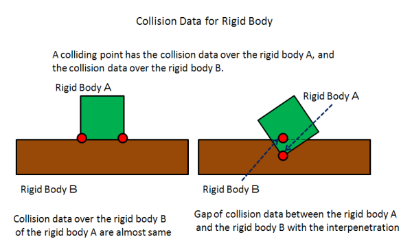
When it is in the state where the rigid body A and the rigid body B have collided, the information on a colliding point is generated by each of the rigid body A and the rigid body B.
Usually, although the position coordinate of the collision data of the rigid body A and the rigid body B is almost the same,
when a penetration arises between the rigid body A and the rigid body B by strong external force etc. for a moment,
a gap arises in the position coordinate of the collision data over the rigid body A and the rigid body B.

Now we will look at the actual code.
First of all, a small square is set to the vertex buffer of debug rendering in order to render a colliding point.

public class PrimitiveScene : PhysicsScene
    {
            ...
            ...
            ...

    private VertexBuffer colVert = null;

            ...
            ...
            ...


    public PrimitiveScene()
    {

            ...
            ...
            ...

        // VertexBuffer for contact points debug rendering
        {
            colVert = new VertexBuffer(4, VertexFormat.Float3);

            const float scale = 0.2f;

            float[] vertex = new float[]
            {
                -1.0f, -1.0f, 0.0f,
                1.0f, -1.0f, 0.0f,
                1.0f, 1.0f, 0.0f,
                -1.0f, 1.0f, 0.0f
            };

            for (int i = 0; i < 12; i++)
                vertex[i] = vertex[i] * scale;

            colVert.SetVertices(0, vertex);
        }
Although it is good not to be a square as for the object for rendering colliding point, because simple information may be sufficient here, it is set as the square.
// Debug rendering for contact points(RigidBody A <=> RigidBody B) and AABB(Axis Aligned Bounding Box)
public override void DrawAdditionalInfo(ref GraphicsContext graphics, ref ShaderProgram program, Matrix4 renderMatrix)
{
    // Draw contact points
    graphics.SetVertexBuffer(0, colVert);

    for (uint i = 0; i < numPhysicsSolverPair; i++)
    {
        // Collision point for RigidBody A
        {
            Matrix4 transMatrix = Matrix4.Translation(
                new Vector3(solverPair[i].resA.X, solverPair[i].resA.Y, 0.0f));

            Matrix4 WorldMatrix = renderMatrix * transMatrix;
            program.SetUniformValue(0, ref WorldMatrix);

            Vector3 color = new Vector3(1.0f, 0.0f, 0.0f);
            program.SetUniformValue(1, ref color);

            graphics.DrawArrays(DrawMode.TriangleFan, 0, 4);
        }

        // Collision point for RigidBody B
        {
            Matrix4 transMatrix = Matrix4.Translation(
                new Vector3(solverPair[i].resB.X, solverPair[i].resB.Y, 0.0f));
            Matrix4 WorldMatrix = renderMatrix * transMatrix;
            program.SetUniformValue(0, ref WorldMatrix);

            Vector3 color = new Vector3(1.0f, 0.0f, 0.0f);
            program.SetUniformValue(1, ref color);

            graphics.DrawArrays(DrawMode.TriangleFan, 0, 4);
        }
    }
Since the number of the colliding points in a scene is saved at numPhysicsSolverPair and a colliding point is saved in solverPair array, only the number of times of numPhysicsSolverPair performs rendering processing of a colliding point in order.

The position of the colliding point by the side of the rigid body A in collision data is acquired by the following.

Matrix4 transMatrix = Matrix4.Translation(
    new Vector3(solverPair[i].resA.X, solverPair[i].resA.Y, 0.0f));
The position of the colliding point by the side of the rigid body B in collision data is acquired by the following.
Matrix4 transMatrix = Matrix4.Translation(
    new Vector3(solverPair[i].resB.X, solverPair[i].resB.Y, 0.0f));

Debug Rendering of Bounding Box


Next we will check the portion which is carrying out debug rendering of the bounding box information.
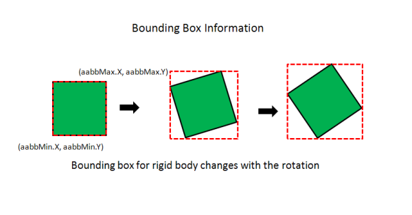
A bounding box is parallel to the X-axis and the Y-axis, and it is a thing of the minimum box which wraps a rigid body.
alternate text
The vertex buffer for rendering a bounding box is first prepared like collision information rendering.
public class PrimitiveScene : PhysicsScene
    {
            ...
            ...
            ...

    private VertexBuffer aabbVert = null;

            ...
            ...
            ...

    public PrimitiveScene()
    {

            ...
            ...
            ...

        // VertexBuffer for AABB debug rendering
        {
            aabbVert = new VertexBuffer(5, VertexFormat.Float3);

            float[] vertex = new float[]
            {
                0.0f, 0.0f, 0.0f,
                1.0f, 0.0f, 0.0f,
                1.0f, 1.0f, 0.0f,
                0.0f, 1.0f, 0.0f,
                0.0f, 0.0f, 0.0f,
            };

            aabbVert.SetVertices(0, vertex);
        }

The bounding box is prepared five points as the vertex, in order to perform line rendering, and it makes the last vertex as well as the first vertex.

// Debug rendering for contact points(RigidBody A <=> RigidBody B) and AABB(Axis Aligned Bounding Box)
public override void DrawAdditionalInfo(ref GraphicsContext graphics, ref ShaderProgram program, Matrix4 renderMatrix)
{

        ...
        ...
        ...

    // Draw AABB Bounding Box
    graphics.SetVertexBuffer(0, aabbVert);

    for (uint i = 0; i < numBody; i++)
    {

        Matrix4 scaleMatrix = new Matrix4(
             sceneBodies[i].aabbMax.X - sceneBodies[i].aabbMin.X, 0.0f, 0.0f, 0.0f,
             0.0f, sceneBodies[i].aabbMax.Y - sceneBodies[i].aabbMin.Y, 0.0f, 0.0f,
             0.0f, 0.0f, 1.0f, 0.0f,
             0.0f, 0.0f, 0.0f, 1.0f
         );

        Matrix4 transMatrix = Matrix4.Translation(
            new Vector3(sceneBodies[i].aabbMin.X, sceneBodies[i].aabbMin.Y, 0.0f));

        Matrix4 WorldMatrix = renderMatrix * transMatrix * scaleMatrix;
        program.SetUniformValue(0, ref WorldMatrix);

        Vector3 color = new Vector3(1.0f, 1.0f, 0.0f);
        program.SetUniformValue(1, ref color);

        graphics.DrawArrays(DrawMode.LineStrip, 0, 5);
    }
The size and position of a bounding box change with a rigid body.
The angle of a bounding box is not based on a rigid body, but always becomes parallel to the X-axis and the Y-axis.
Since the state of the rigid body is saved in sceneBodies array and the information on the size of a bounding box is saved at the value of aabbMax and aabbMin, it renders using it.

Acquisition of the size of a bounding box

Matrix4 scaleMatrix = new Matrix4(
     sceneBodies[i].aabbMax.X - sceneBodies[i].aabbMin.X, 0.0f, 0.0f, 0.0f,
     0.0f, sceneBodies[i].aabbMax.Y - sceneBodies[i].aabbMin.Y, 0.0f, 0.0f,
     0.0f, 0.0f, 1.0f, 0.0f,
     0.0f, 0.0f, 0.0f, 1.0f
 );

Acquisition of the position of a bounding box

Matrix4 transMatrix = Matrix4.Translation(
    new Vector3(sceneBodies[i].aabbMin.X, sceneBodies[i].aabbMin.Y, 0.0f));

After adjusting the size of a bounding box, in order to render in the right position, the matrix for rendering is set up in the following turn.

  1. scaleMatrix
  2. transMatrix
Matrix4 WorldMatrix = renderMatrix * transMatrix * scaleMatrix;
In addition, resources, such as a vertex buffer prepared for these debug rendering, should be required to release
at the time of the end of a scene, or a change, and should make it removed.

Below in PrimitiveScene, the vertex buffer for rigid body rendering and the vertex buffer for debugging information rendering are released.
public override void ReleaseScene()
{
    for (int i = 0; i < numShape; i++)
        if(vertices[i] != null)
            vertices[i].Dispose();

    if(aabbVert != null) aabbVert.Dispose();
    if(colVert != null) colVert.Dispose();
}
Although the outline of PrimitiveScene has been seen above, we recommend you to attempt how for a result to change on modifying actually various values.

Joint Setting

The sample scene JointScene is seen as an example of a setup of joint.
"sample/Physics2D/Physics2DSample/BasicScene/JointScene.cs"

Joint is the constraint set up between two rigid bodies.
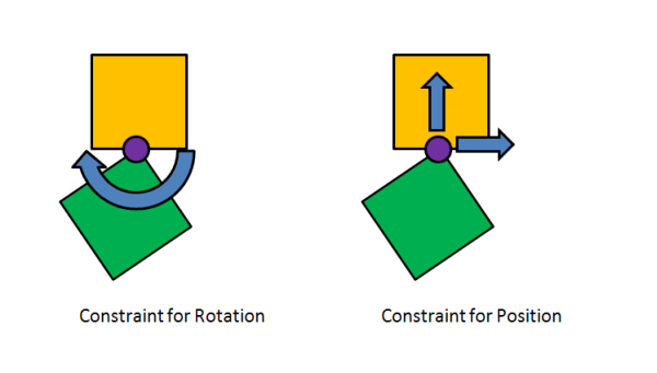
There are constraint of position and rotation for the joint between two rigid bodies.
  1. Constraint of Rotation(Rotation Free, Fixed, Limited)
  2. Constraint of Position (Position Free, Fixed, Limited)
In addition, the joint between a static rigid body and a static rigid body do not have any meanings and we should take care not to set up those joints.
alternate text
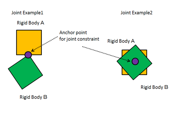
In joint connection, a setup of the anchor point of at which point to connect a rigid body and a rigid body,
specification of a constration of rotation and position are required.
alternate text

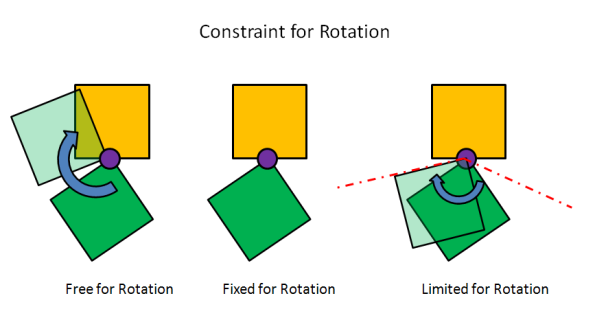
For the rigid body A and the rigid body B which were combined at joint center on an anchor point in the constraint of rotation.

  • Free for rotation
  • Fixed for rotation
  • Limited for rotation

can be set.

alternate text

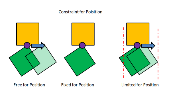
For the rigid body A and the rigid body B which were combined at joint center on an anchor point in the constraint of position

  • Free for position
  • Fixed for position
  • Limited for position

can be set.

alternate text
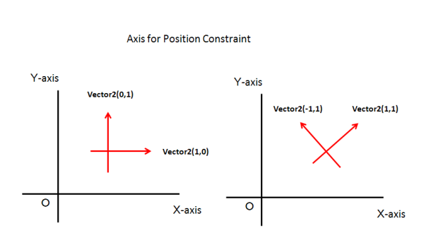
For the constraint of position, two axes which go mutually are necessary.
Usually, it is although it specifies to the X-axis and the Y-axis, even if it is not the X-axis and the Y-axis,
as far as it is two axes which go direct mutually, it can set up. For example, Vector2(1, 1) and Vector2(-1, 1)
alternate text

Fixed both for rotation and position

public override void InitScene ()
{

        ...
        ...
        ...

        // Link a box rigid body to the scene with a fixed joint.
        // If you just want to fix a rigid body to the scene perfectly, it is best simply making a static rigidbody.
        {
                sceneBodies[numBody] = new PhysicsBody(sceneShapes[2], 10.0f);
                sceneBodies[numBody].position = new Vector2(-30.0f, 0.0f);
                sceneBodies[numBody].shapeIndex = 2;
                numBody++;

                PhysicsBody b1 = sceneBodies[0];
                PhysicsBody b2 = sceneBodies[numBody-1];
                sceneJoints[numJoint] = new PhysicsJoint(b1, b2, (b2.position), 0, (uint)numBody-1);
                sceneJoints[numJoint].axis1Lim = new Vector2(1, 0);
                sceneJoints[numJoint].axis2Lim = new Vector2(0, 1);
                sceneJoints[numJoint].angleLim = 1;
                numJoint++;
        }
A joint constraint is generated between the 0th rigid body and the (numBody-1)th rigid body here.
The 0th rigid body is a static rigid body of the floor in a scene.

As the generation method of joint constraint, specification of the rigid body pair which makes joint, and specification of an anchor point are needed.
PhysicsBody b1 = sceneBodies[0];
PhysicsBody b2 = sceneBodies[numBody-1];
sceneJoints[numJoint] = new PhysicsJoint(b1, b2, (b2.position), 0, (uint)numBody-1);
Since the anchor point is specified as (b2.position) here, the center of the (numBody-1)th rigid body of is used as the anchor point.
After generating joint, the portion which specifies the constraint condition is the following.
sceneJoints[numJoint].axis1Lim = new Vector2(1, 0);
sceneJoints[numJoint].axis2Lim = new Vector2(0, 1);
sceneJoints[numJoint].angleLim = 1;
  1. Fixed for Vector2(1, 0) direction
  2. Fixed for Vector2(0, 1) direction
  3. Fixed for rotation

Specification is performed in this order.

And you can check the following here.

sceneJoints[numJoint].angleLim = 0;

Supposing that there is this condition, it means that this constraint is free for rotation.

The similar thing comes out.

sceneJoints[numJoint].axis1Lim = new Vector2(0, 0);

Supposing that there is this condition, constraint for X-axis is removed, and it means free for X-axis.

The similar thing comes out.

sceneJoints[numJoint].axis2Lim = new Vector2(0, 0);

Supposing that there is this condition, constraint for Y-axis is removed, and it means free for Y-axis.

sceneJoints[numJoint].axis1Lim = new Vector2(0, 0);
sceneJoints[numJoint].axis2Lim = new Vector2(0, 0);
sceneJoints[numJoint].angleLim = 0;

Supposing that there is this condition, then there are no constraint condition at all, ant it will be the same as well as the scene which does not have any constraints.

Example of Constraint for Rotation

public override void InitScene ()
{

...
...
...

        // Link a box rigid body to the scene with a rotation joint(with angle constraints)
        {
                sceneBodies[numBody] = new PhysicsBody(sceneShapes[2], 10.0f);
                sceneBodies[numBody].position = new Vector2(-20.0f, 0.0f);
                sceneBodies[numBody].shapeIndex = 2;
                numBody++;

                PhysicsBody b1 = sceneBodies[0];
                PhysicsBody b2 = sceneBodies[numBody-1];
                sceneJoints[numJoint] = new PhysicsJoint(b1, b2, (b2.position), 0, (uint)numBody-1);
                sceneJoints[numJoint].axis1Lim = new Vector2(1, 0);
                sceneJoints[numJoint].axis2Lim = new Vector2(0, 1);
                sceneJoints[numJoint].angleLim = 1;
                sceneJoints[numJoint].angleLower = PhysicsUtility.GetRadian(-45.0f);
                sceneJoints[numJoint].angleUpper = PhysicsUtility.GetRadian(45.0f);
                numJoint++;
        }

It is the following portions that are performing -45 degree to 45 degree with restrictions for rotation.

sceneJoints[numJoint].angleLim = 1;
sceneJoints[numJoint].angleLower = PhysicsUtility.GetRadian(-45.0f);
sceneJoints[numJoint].angleUpper = PhysicsUtility.GetRadian(45.0f);
Although restriction of rotation has started, not only angleLim but angleLower and angleUpper are specified,
and -45 degrees and 45 degrees are specified, respectively.
angleLower and angleUpper are the variables which set up the minimum and maximum of rotation restrictions.
In addition, it is necessary to specify the angle by radian.

Example of Constraint for Vertical

public override void InitScene ()
{

...
...
...

        // Link a box rigid body to the scene with a horizontal slider joint (with movement constraints)
        {
                sceneBodies[numBody] = new PhysicsBody(sceneShapes[2], 10.0f);
                sceneBodies[numBody].position = new Vector2(0.0f, 0.0f);
                sceneBodies[numBody].shapeIndex = 2;
                numBody++;

                PhysicsBody b1 = sceneBodies[0];
                PhysicsBody b2 = sceneBodies[numBody-1];
                sceneJoints[numJoint] = new PhysicsJoint(b1, b2, (b2.position), 0, (uint)numBody-1);
                sceneJoints[numJoint].axis1Lim = new Vector2(1, 0);
                sceneJoints[numJoint].axis2Lim = new Vector2(0, 1);
                sceneJoints[numJoint].axis2Lower = -10.0f;
                sceneJoints[numJoint].axis2Upper = 10.0f;
                sceneJoints[numJoint].angleLim = 1;
                numJoint++;
        }

It is the following portions that are performing the constraint from -10 m to +10 m with Y-axis restrictions.

sceneJoints[numJoint].axis2Lim = new Vector2(0, 1);
sceneJoints[numJoint].axis2Lower = -10.0f;
sceneJoints[numJoint].axis2Upper = 10.0f;
Although restriction of Y-axis has started, not only axis2Lim but axis2Lower and axis2Upper are specified,
Therefore, rigid body can move now in the direction of the Y-axis freely with restrictions from an anchor point between -10m and +10m.
axis2Lower and axis2Upper are the variables which set up the minimum and maximum of position constraint.

Example of Constraint for Horizontal

public override void InitScene ()
{

...
...
...

// Link a box rigid body to the scene with a horizontal slider joint (with movement constraints)
{
        sceneBodies[numBody] = new PhysicsBody(sceneShapes[2], 10.0f);
        sceneBodies[numBody].position = new Vector2(0.0f, 0.0f);
        sceneBodies[numBody].shapeIndex = 2;
        numBody++;

        PhysicsBody b1 = sceneBodies[0];
        PhysicsBody b2 = sceneBodies[numBody-1];
        sceneJoints[numJoint] = new PhysicsJoint(b1, b2, (b2.position), 0, (uint)numBody-1);
        sceneJoints[numJoint].axis1Lim = new Vector2(1, 0);
        sceneJoints[numJoint].axis1Lower = -10.0f;
        sceneJoints[numJoint].axis1Upper = 10.0f;
        sceneJoints[numJoint].axis2Lim = new Vector2(0, 1);
        sceneJoints[numJoint].angleLim = 1;
        numJoint++;

    // The horizontal slider joint is quite slippy,
    // so to make the rigid body stop we add some air friction
        b2.airFriction = 0.01f;
}

Horizontal restrictions are set up like the example of the move restrictions which can be set to vertical.

sceneJoints[numJoint].axis1Lim = new Vector2(1, 0);
sceneJoints[numJoint].axis1Lower = -10.0f;
sceneJoints[numJoint].axis1Upper = 10.0f;
Therefore, rigid body can move now in the direction of the X-axis freely with restrictions from an anchor point between -10m and +10m.

It may arise that the object which is moving horizontally does not stop easily
because gravity is not applied horizontally when movement is horizontally permitted with restrictions here,
therefore it has set up to give air resistance to a rigid body.
// The horizontal slider joint is quite slippy,
// so to make the rigid body stop we add some air friction
b2.airFriction = 0.01f;
The air resistance coefficient of 0.01f is given to the (numBody-1)th rigid body,
and it has prevented continuing sliding minutely horizontally by air resistance.